Saturday, January 28, 2017


1  AC - Alternating current
2  ACDRVAC - adapter to system - switch driver output
3  ACGOOD - Valid adapter detect active-low open - drain logic output
4  ACN - Adapter current sense negatif
5  ACP - Adapter current sense positif
6  ACOP - Input Over - Power Protection
7  ACOV - Input Overvoltage Protection
8  ACP - Adapter current sense resistor , positive input .
9  ALWP - Always on power +B : Ac power rail or bat for power circuit
10  BATT - BATTERYBOM : BILL OF MATERIALS MANAGEMENT
11  BT - Buttonchgen : Charge active-low enable input logic
12  CIN - Input Capacitor
13  CLK_EN - Clock enable
14  CON - Conector
15  CRT - Cathode ray tube
16  DC - Direct current17  DM - DIM / DIM SOCKET / SOCKET MEMORY / JACK
18  DDRDOCK - Docking socket
19  EMI - Electromagnetic Interference ( Electromagnetic interference )
20  F - FUSE
21  FSEL - Frequency Select Input
22  GND - Ground
23  GP - GROUND PIN
24  HDMI - High - Definition Multimedia Interface
25  CID - Continuous Drain CurrentI
26  DM - Pulsed Drain Current
37  IN ( SHDN ) - Shutdown Supply Current
38  IIN - Operating Supply CurrentI
39  IIN - ( STBY ) Standby Supply Current
30 IS - Continuous Source Current ( Diode Conduction )
31  Ivin - Battery Supply Current at VIN pin
32  JP - Jumper point
33  LCDV - LCD Powerl
34  GATE- Lower -side MOSFET gate signal
35  LPC Low Pin Count
36  LVDS - Low - voltage differential signaling ( SYSTEM PENSIGNALAN )
47  MBAT - MAIN BATTERY
48  ODD - OUTPUT DISC DRIVE
49  PCI - Peripheral Component Interconnect
40 PGOOD - Power good open - drain output
41  PIR - IMPROVED PRODUCT RECORDPSI # : Current input indicator
42  PVCC - positive power supply
43  ICRTC - Real time clock
44  TD - Death TimeTHRM : Thermal sensor
45  TMDS - Transition Minimized Differential Signaling ( Data Transmissions technology )
46  TP - Test Point
57  TPAD - Thermal pad
58  UVLO - Input undervoltage lock -out
59  V - VOLTAGE
50  +V - pwr more(+3 v=more than 3 volt) VADJ :Output voltage regulation
51  VALW - Always on power
52  VALWP - VALW PADVBAT : Battery power
53  VCCP - power chip ( ich , graphic chips )
54  VCORE - POWER processors ( vCPU )
55  VDD - control power supply
56  VDDR - POWER DDR ( VDRAM / VRAM / Vmem )
57  VDS - DRAIN SOURCE VOLTAGE
58  VFB - feedback inputs Power
59  VGS - Gate voltage source
60  SVIN - Input Voltage Range
61  VIN - Adapter power supply ( vol_in )
62  VL - Power Lock
63  VL - voltage across the load / resistor load voltage
64  VLDOIN - Power supply of the VTT and VTTREF output stage (to Powermos)
65  VOT - Volt_out
66  VRAM - Power Random acses memory
67  VREF - POWER REFERENCES / SCHEMA REFERENCE / DEMAND
68  SCHEMEVS - SUITCH POWER/voltage on switch
69  VS + - Voltage support
70  VSB - Power switch button
71  VSS - Signal ground
72  VSW - POWER SWICT
73  VUSB - USB POWER/voltage USB
74  VVGA - POWER VGA ( VGPX / VGPU / VCVOD


Friday, January 27, 2017


 Short for Basic Input/Output System, the BIOS (pronounced bye-oss) is a ROM chip located on all motherboards that allows you to access and set up your computer system at the most basic level. In the picture below, is an example of what a BIOS chip may look like on your computer motherboard. In this example, this is a picture of an early AMIBIOS, a type of BIOS manufactured by the AMI. Another good example of a BIOS manufacturer is Phoenix.


The BIOS includes instructions on how to load basic computer hardware and includes a test referred to as a POST (Power On Self Test) that helps verify the computer meets requirements to boot up properly. If the computer does not pass the POST, you will receive a combination of beeps indicating what is malfunctioning within the computer.


  • POST - Test the computer hardware and make sure no errors exist before loading the operating system. Additional information on the POST can be found on our POST and Beep Codes page.
  • Bootstrap Loader - Locate the operating system. If a capable operating system is located, the BIOS will pass control to it.
  • BIOS drivers - Low level drivers that give the computer basic operational control over your computer's hardware.
  • BIOS or CMOS Setup - Configuration program that allows you to configure hardware settings including system settings such as computer passwords, time, and date.

Friday, January 20, 2017

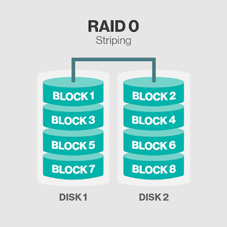
RAID (redundant array of independent disks; originally redundant array of inexpensive disks) provides a way of storing the same data in different places (thus, redundantly) on multiple hard disks (though not all RAID levels provide redundancy). By placing data on multiple disks, input/output (I/O) operations can overlap in a balanced way, improving performance. Since multiple disks increase the mean time between failures (MTBF), storing data redundantly also increases fault tolerance.

RAID arrays appear to the operating system (OS) as a single logical hard disk. RAID employs the technique of disk mirroring or disk striping, which involves partitioning each drive's storage space into units ranging from a sector (512 bytes) up to several megabytes. The stripes of all the disks are interleaved and addressed in order.
In a single-user system where large records, such as medical or other scientific images, are stored, the stripes are typically set up to be small (perhaps 512 bytes) so that a single record spans all disks and can be accessed quickly by reading all disks at the same time.
In a multi-user system, better performance requires establishing a stripe wide enough to hold the typical or maximum size record. This allows overlapped disk I/O across drives.

Standard RAID levels

RAID 0: This configuration has striping but no redundancy of data. It offers the best performance but no fault-tolerance.
RAID 1: Also known as disk mirroring, this configuration consists of at least two drives that duplicate the storage of data. There is no striping. Read performance is improved since either disk can be read at the same time. Write performance is the same as for single disk storage.
RAID 2: This configuration uses striping across disks with some disks storing error checking and correcting (ECC) information. It has no advantage over RAID 3 and is no longer used.
RAID 3: This technique uses striping and dedicates one drive to storing parity information. The embedded ECC information is used to detect errors. Data recovery is accomplished by calculating the exclusive OR (XOR) of the information recorded on the other drives. Since an I/O operation addresses all drives at the same time, RAID 3 cannot overlap I/O. For this reason, RAID 3 is best for single-user systems with long record applications.
RAID 4: This level uses large stripes, which means you can read records from any single drive. This allows you to use overlapped I/O for read operations. Since all write operations have to update the parity drive, no I/O overlapping is possible. RAID 4 offers no advantage over RAID 5.
RAID 5This level is based on block-level striping with parity. The parity information is striped across each drive, allowing the array to function even if one drive were to fail. The array’s architecture allows read and write operations to span multiple drives. This results in performance that is usually better than that of a single drive, but not as high as that of a RAID 0 array. RAID 5 requires at least three disks, but it is often recommended to use at least five disks for performance reasons.
RAID 5 arrays are generally considered to be a poor choice for use on write-intensive systems because of the performance impact associated with writing parity information. When a disk does fail, it can take a long time to rebuild a RAID 5 array. Performance is usually degraded during the rebuild time and the array is vulnerable to an additional disk failure until the rebuild is complete.


Thursday, January 19, 2017


Until recently, PC buyers had very little choice about what kind of storage to get in a laptop or desktop. If you bought an ultraportable, you likely had a solid-state drive (SSD) as the primary drive (C: on Windows, Macintosh HD on a Mac). Every other desktop or laptop form factor had a hard disk drive (HDD). Now, you can configure your system with either an HDD or an SSD, or in some cases both. But how do you choose? We explain the differences between SSDs and HDDs (or hard drives), and walk you through the advantages and disadvantage of both to help you decide.

HDD and SSD Explained

The traditional spinning hard drive is the basic nonvolatile storage on a computer. That is, information on it doesn't "go away" when you turn off the system, as is the case with data stored in RAM. A hard drive is essentially a metal platter with a magnetic coating that stores your data, whether weather reports from the last century, a high-definition copy of the Star Wars trilogy, or your digital music collection. A read/write head on an arm accesses the data while the platters are spinning.
An SSD does functionally everything a hard drive does, but data is instead stored on interconnected flash memory chips that retain the data even when there's no power present. The chips can either be permanently installed on the system's motherboard (as on some small laptops and ultraportables), on a PCI Express (PCIe) card (in some high-end workstations and an increasing number of bleeding-edge consumer systems), or in a box that's sized, shaped, and wired to slot in for a laptop or desktop's hard drive (common on everything else). These flash memory chips are of a different type than is used in USB thumb drives, and are typically faster and more reliable. SSDs are consequently more expensive than USB thumb drives of the same capacities.
Note: We'll be talking primarily about internal drives in this story, but almost everything applies to external hard drives as well. External drives come in both large desktop and compact portable form factors, and SSDs are gradually becoming a larger part of the external market.

A History of HDDs and SSDs

Hard drive technology is relatively ancient (in terms of computer history, anyway). There are well-known pictures of the infamous IBM 350 RAMAC hard drive from 1956 that used 50 24-inch-wide platters to hold a whopping 3.75MB of storage space. This, of course, is the size of an average 128Kbps MP3 file today, in the physical space that could hold two commercial refrigerators. The RAMAC 350 was only limited to government and industrial uses, and was obsolete by 1969. Ain't progress wonderful? The PC hard drive form factor standardized at 5.25 inches in the early 1980s, with the 3.5-inch desktop-class and 2.5-inch notebook-class drives coming soon thereafter. The internal cable interface has changed from serial to IDE (now frequently called parallel ATA, or PATA) to SCSI to serial ATA (SATA) over the years, but each essentially does the same thing: connect the hard drive to the PC's motherboard so your data can be processed. Today's 2.5- and 3.5-inch drives mainly use SATA interfaces (at least on most PCs and Macs), though some high-speed SSDs use the faster PCIe interface instead. Capacities have grown from multiple megabytes to multiple terabytes, more than a million-fold increase. Current 3.5-inch hard drives have capacities as high as 10TB, with 2.5-inch drives maxing out at 5TB.
The SSD has a much shorter history. There was always an infatuation with nonmoving storage from the beginning of personal computing, with technologies like bubble memory flashing (pun intended) and dying in the 1970s and 1980s. Current flash memory is the logical extension of the same idea, as it doesn't require constant power to retain the data you store on it. The first primary drives that we know as SSDs started during the rise of netbooks in the late 2000s. In 2007, the OLPC XO-1 used a 1GB SSD, and the Asus Eee PC 700 series used a 2GB SSD as primary storage. The SSD chips on low-end Eee PC units and the XO-1 were permanently soldered to the motherboard. As netbooks and other ultraportable laptop PCs became more capable, SSD capacities increased and eventually standardized on the 2.5-inch notebook form factor. This way, you could pop a 2.5-inch hard drive out of your laptop or desktop and replace it easily with an SSD. Other form factors emerged, like the mSATA Mini PCIe SSD card, M.2 SSD in SATA and PCIe variants, and the DIMM-like solid-state Flash Storage in the Apple MacBook Air and MacBook Pro, but today many SSDs still use the 2.5-inch form factor. The 2.5-inch SSD capacity currently tops out at 4TB, but a 16TB version for enterprise devices like servers was released by Samsung in early 2016.

Advantages and Disadvantages

Both SSDs and hard drives do the same job: They boot your system, and store your applications and personal files. But each type of storage has its own unique feature set. How do they differ, and why would you want to get one over the other?
Price: SSDs are more expensive than hard drives in terms of dollar per gigabyte. A 1TB internal 2.5-inch hard drive costs between $40 and $50, but as of this writing, an SSD of the same capacity and form factor starts at $230. That translates into 4 to 5 cents per gigabyte for the hard drive and 23 cents per gigabyte for the SSD. Since hard drives use older, more established technology, they will remain less expensive for the near future. Those extra hundreds for the SSD may push your system price over budget.
Maximum and Common Capacity: Although SSD units top out at 4TB, those are still rare and expensive. You're more likely to find 500GB to 1TB units as primary drives in systems. While 500GB is considered a "base" hard drive in 2016, pricing concerns can push that down to 128GB for lower-priced SSD-based systems. Multimedia users will require even more, with 1TB to 4TB drives common in high-end systems. Basically, the more storage capacity, the more stuff you can keep on your PC. Cloud-based (Internet) storage may be good for housing files you plan to share among your phone, tablet, and PC, but local storage is less expensive, and you only have to buy it once
Fragmentation: Because of their rotary recording surfaces, hard drives work best with larger files that are laid down in contiguous blocks. That way, the drive head can start and end its read in one continuous motion. When hard drives start to fill up, large files can become scattered around the disk platter, causing the drive to suffer from what's called fragmentation. While read/write algorithms have improved to the point that the effect is minimized, hard drives can still become fragmented. SSDs can't, however, because the lack of a physical read head means data can be stored anywhere. Thus, SSDs are inherently faster.
Durability: An SSD has no moving parts, so it is more likely to keep your data safe in the event you drop your laptop bag or your system is shaken about by an earthquake while it's operating. Most hard drives park their read/write heads when the system is off, but they are flying over the drive platter at a distance of a few nanometers when they are in operation. Besides, even parking brakes have limits. If you're rough on your equipment, an SSD is recommended.
Availability: Hard drives are more plentiful in budget and older systems, but SSDs are becoming more prevalent in recently released laptops. That said, the product lists from Western Digital, Toshiba, Seagate, Samsung, and Hitachi are still skewed in favor of hard drive models over SSDs. For PCs and Mac desktops, internal hard drives won't be going away completely, at least for the next couple of years. SSD model lines are growing in number: Witness the number of thin laptops with 256 to 512GB SSDs installed in place of hard drives.

Tuesday, January 17, 2017

There are three types of SMPSs. They are AT, ATX, BTX. These three types of SMPSs have different connectors and each wire has different voltages. Here the connectors and itsvoltages.


AT SMPSs have 12 pin power connector, ATX SMPSs have 20 pin power connector and BTX SMPSs have 24 and 28 pin power connectors. AT power supplies were used in 80’s and from 1996 we use ATX power supplies.  Here are the AT, ATX and BTX SMPSsvoltages and users.

Smps                                 AT                   ATX                   BTX 

Red                                 +5v                    +5v                     +5v
Yellow                             +12v                  +12v                   +12v
Blue                                 -12v                  -12v                     -12v
White                               -5v                    -5v                       -5v
Black                                0v                      0v                       0v
Orange                            +5v                   +3.3v                   +3.3v
Green                               ----                    +5v                      +5v
Gray or Brown                 ----                    +5v                      +5v
Purple                               ----                    +5v                      +5v


Red                 : it is used for signal sending
Yellow             : It is used for motor running
White &Blue: It is used for backward compatibility
Black               : It is used for grounding purpose
Orange            : It is used for power good signal
Green              : It is used for power supply on in ATX
Gray & Brown: It is used for power good signal in ATX
Purple              : It is used for auto shutdown in ATX

Kategori

Powered by Blogger.

Recent in Sports

Breaking News

top

LinkCollider - Free SEO Tools Plus Social Media Sharing

Popular Posts

Recent Posts